Two pieces run on the GCS computer. Beam is the background server — Somewear’s API wrapper to the backend, shared across Somewear products — and it runs in the Windows system tray. Horizon UI is the Unmanned-specific application Beam opens (the tray labels it Open Horizon Manager); it is the window you work in. This page names every screen and control once, so the procedures elsewhere in this manual can refer to them without re-explaining. Terms in bold are the canonical names used throughout.
Starting Beam and opening Horizon UI
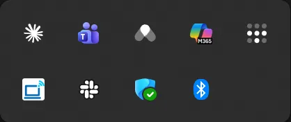
Beam runs in the Windows system tray. Its tray icon sits with the other tray applications.
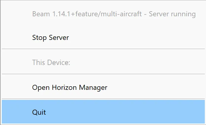
Select the Beam tray icon to open its menu. The top line reports the Beam version and Server running. From here you can Stop Server, Open Horizon Manager (launch Horizon UI), or Quit.
The navigation rail
Horizon UI opens to a fixed navigation rail down the left edge — three screens and two utilities:
| Icon | Destination | What you do there |
|---|---|---|
| USB | Connected Device | Configure the Horizon unit connected to this computer over USB |
| Grid | Fleet View | Monitor the fleet — aircraft flight plans and incoming telemetry |
| Console | Diagnostics | View logs, edit configuration, and run hardware tests |
| ⓘ | Info | Application and version information |
| Gear | Settings | Application settings, GCS connection, and server restart |
Connected Device
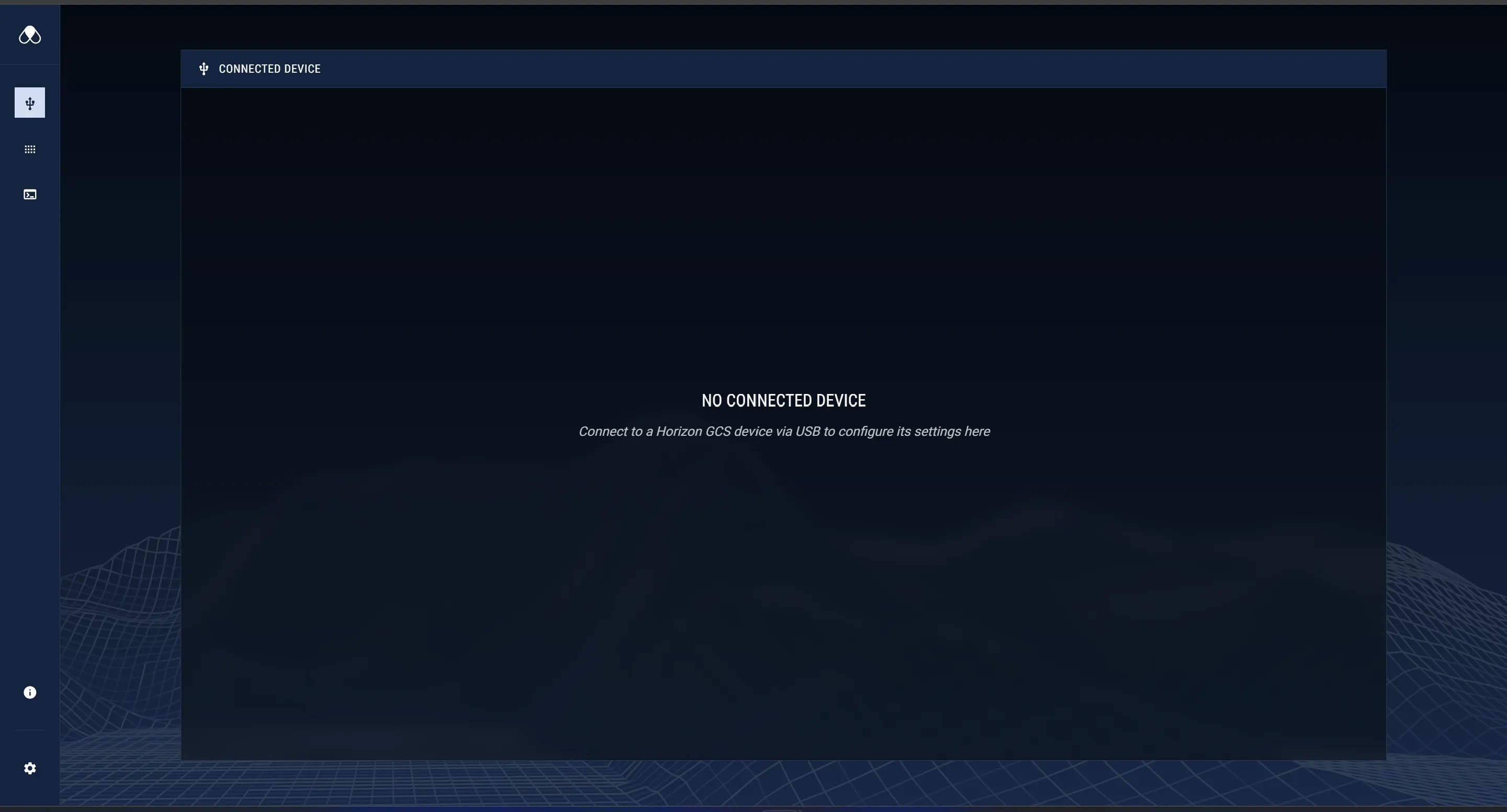
Connected Device configures the single Horizon unit attached to this computer by USB. When no unit is attached, it shows No Connected Device.
The header shows the device Name and Serial, a picture of the unit, its Firmware Version, and a Refresh control. Prefill radio settings from previous device configuration copies the last-used radio settings into the form. The footer tracks edits: when a field changes, You have unsaved changes appears with Discard Changes and Apply Changes — nothing takes effect until you select Apply Changes.
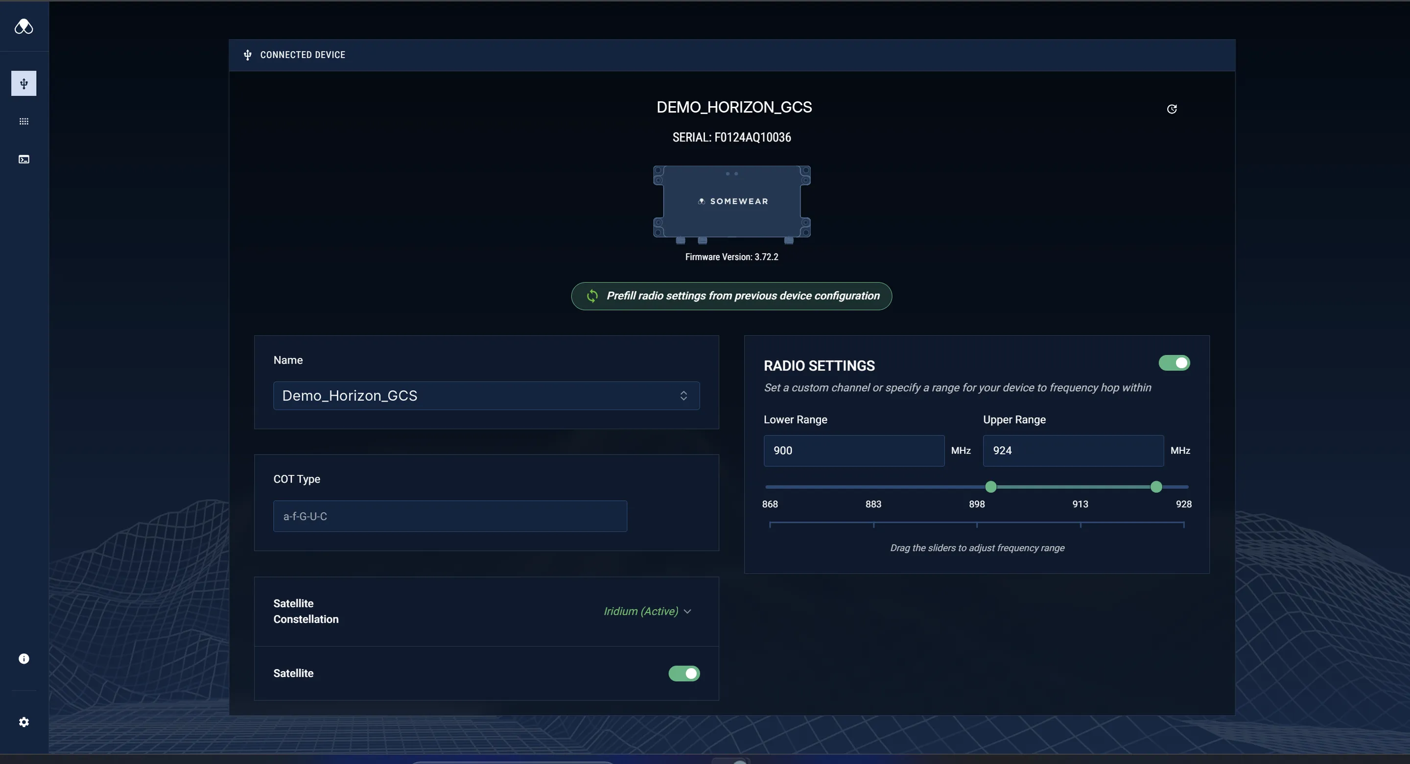
The left column holds device identity and satellite settings:
- Name — the unit’s resource name. Pick an existing resource or Create a new one.
- COT Type — the Cursor-on-Target type used for ATAK integration.
- Satellite Constellation — displays the unit’s constellation, Iridium or Inmarsat, labeled (Active). This is fixed by the unit’s SKU (the constellations use different hardware) and is not switchable in software.
- Satellite — the toggle that enables the BLOS satellite link.
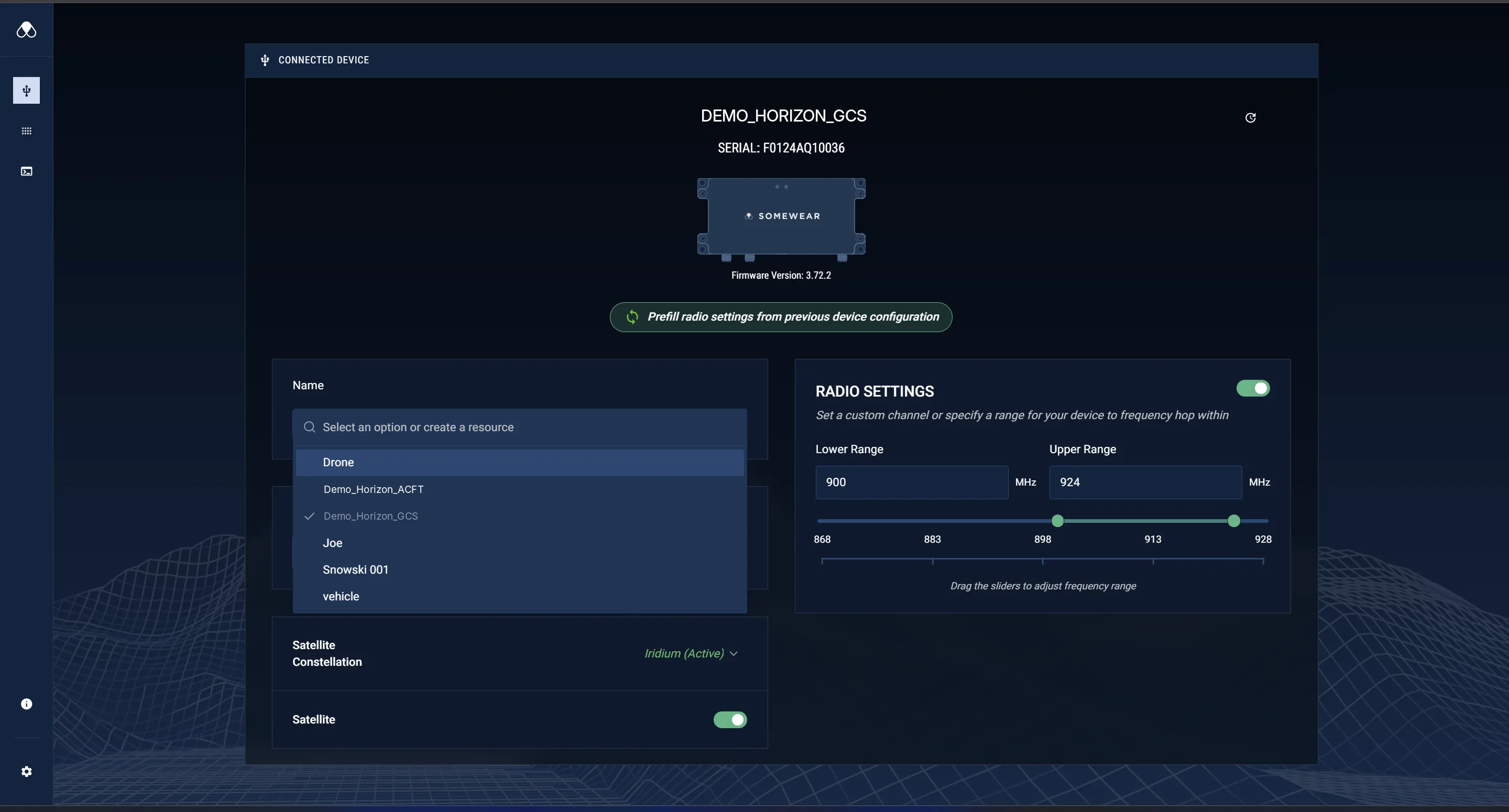
The right column is Radio Settings — the LOS radio configuration:
- The Radio Settings toggle enables the LOS radio.
- Lower Range and Upper Range (in MHz) set the band the unit frequency-hops within, adjusted with the range slider (868–928 MHz).
Set matching ranges on both the Aircraft and GCS units. See LOS & BLOS Radio Specifications for limits.
If no unit is attached over USB, Horizon UI shows No Connected Device with a prompt to connect a Horizon GCS unit. Seat the USB-C cable at both ends and confirm the unit is powered (see LED Quick Reference).
Updating firmware
The Aircraft and GCS roles run different firmware — files ending in _default for the aircraft role, _gcs for the GCS role. To repurpose a unit from one role to the other, update it with the appropriate firmware file here first.
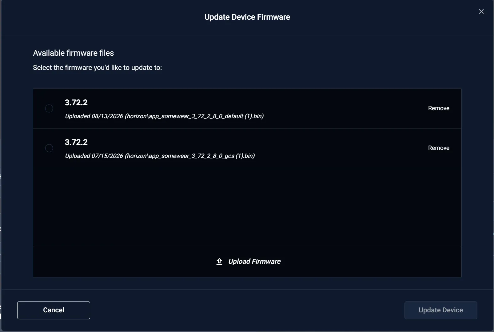
The Update Device Firmware dialog lists Available firmware files with their upload dates and filenames; Upload Firmware adds a new file. Select a firmware entry, then Update Device.
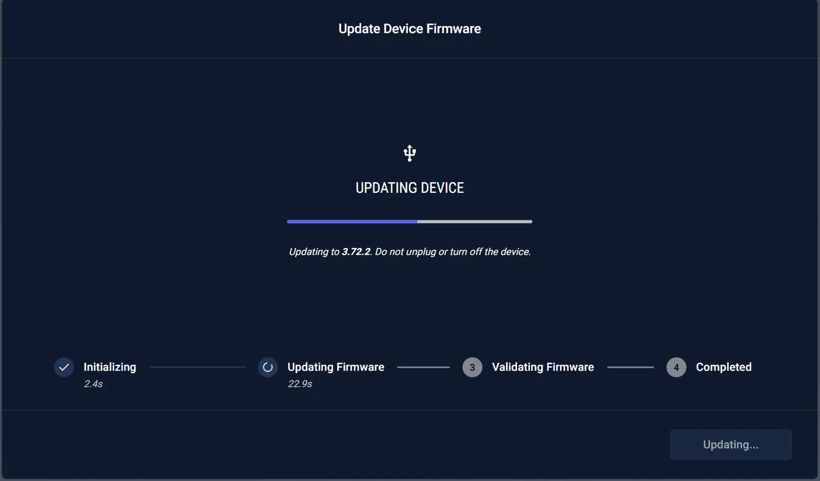
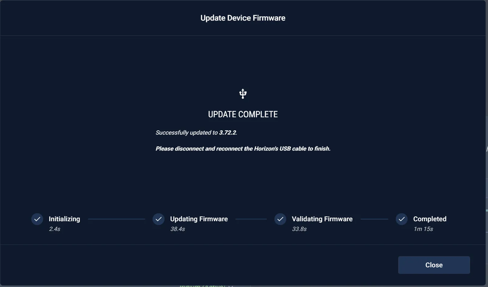
The update steps through Initializing → Updating Firmware → Validating Firmware → Completed and warns Do not unplug or turn off the device. During the update the unit’s STATUS LED flashes amber (see LED Quick Reference).
When it reports Update Complete with all four steps checked, disconnect and reconnect the unit’s USB-C cable to finish, then confirm the new Firmware Version.
Advanced Settings
Advanced Settings (top right of Connected Device) opens a modal that configures the flight-controller serial link and, for payload control, maps equipment to MAVLink output indices — settings most operators never touch. The full procedure is in Payload Control.
Serial Link sets how the unit talks to the flight controller:
- Hardware Flow Control — RTS/CTS on the flight-controller serial connection.
- Baudrate — must match the autopilot telemetry port (
57600for the standard link).
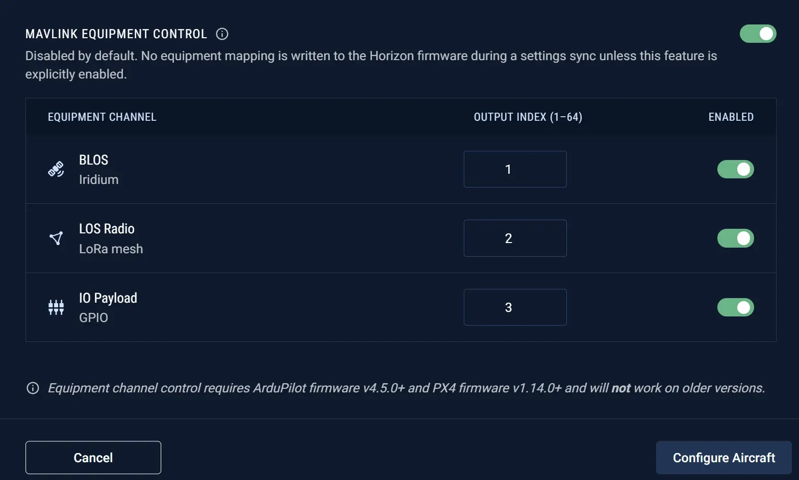
MAVLink Equipment Control (off by default) maps each equipment channel — BLOS (Iridium), LOS Radio (LoRa mesh), and IO Payload (GPIO) — to an Output Index (1–64) with an Enabled toggle. Configure Aircraft writes the mapping to the unit. Hardware flow control and the IO Payload channel share the same GPIO pins, so only one can be enabled at a time.
Fleet View
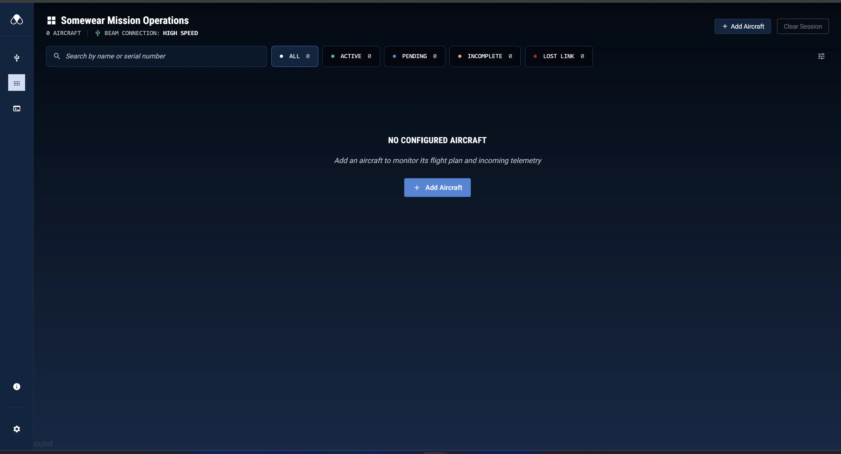
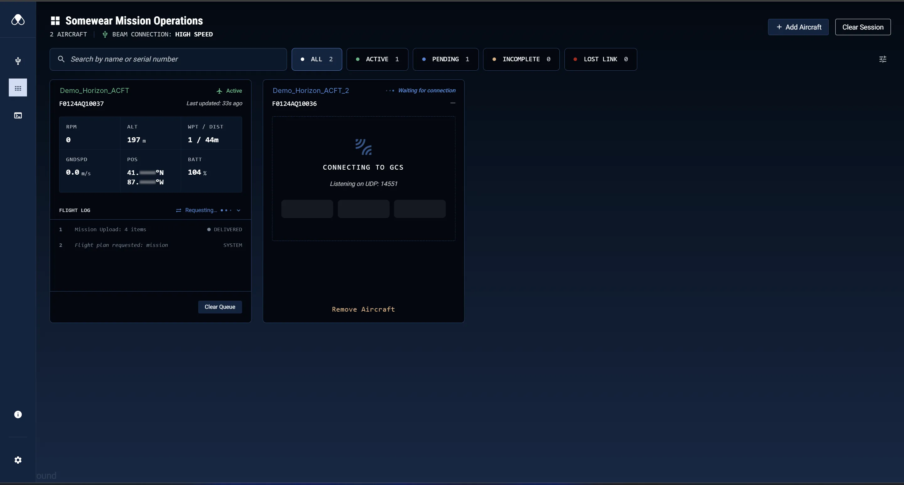
Fleet View (headed Somewear Mission Operations) monitors every aircraft you have added. The header shows the aircraft count and the Beam Connection indicator (for example, High Speed), plus Add Aircraft and Clear Session.
Below the header are a Search field (by name or serial number), the status filters — All, Active, Pending, Incomplete, Lost Link, each with a live count — and a Card Telemetry control. With no aircraft added, Fleet View shows No Configured Aircraft.
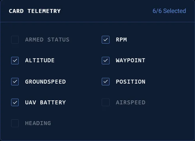
The Card Telemetry control chooses which readings appear on the aircraft cards. Up to six of the nine values — Armed Status, RPM, Altitude, Waypoint, Groundspeed, Position, UAV Battery, Airspeed, Heading — can be shown at once; the selector reports the count (e.g. 6/6 Selected).
Add an aircraft
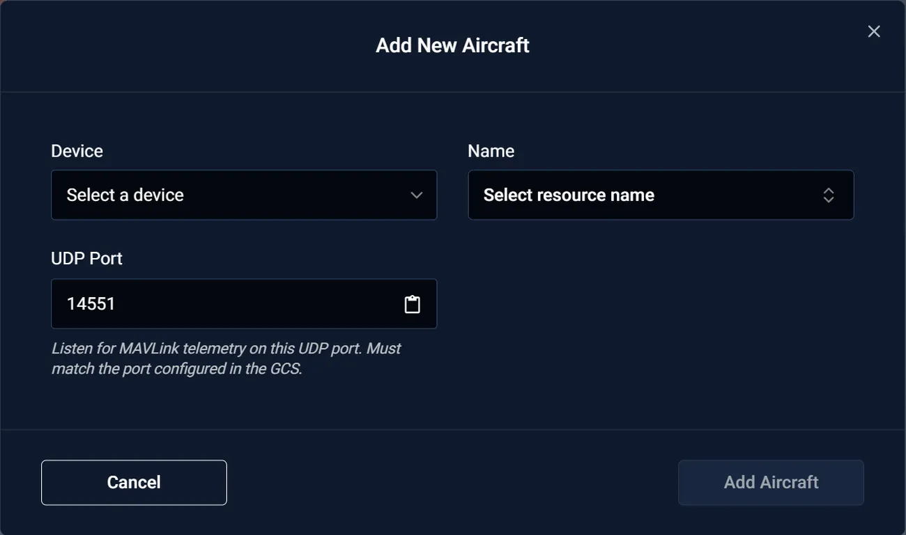
Add Aircraft opens the Add New Aircraft dialog:
- Device — the Horizon unit (by name or serial) that carries this aircraft’s link.
- Name — the aircraft’s resource name; select an existing option or Create a new one.
- UDP Port — the port Horizon UI listens on for MAVLink telemetry. It defaults to 14550 and auto-increments (14551, …) for each additional aircraft. It must match the port configured in the GCS application (see Preferences).
Add Aircraft confirms; it stays disabled until the required fields are set.
The aircraft card
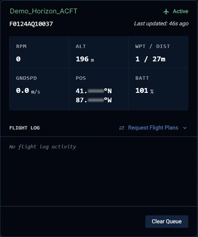
Each added aircraft appears as an aircraft card showing its name, serial, a status, and Last updated time, above the metrics grid you selected in Card Telemetry (RPM, ALT, WPT / DIST, GNDSPD, POS, BATT by default). Below the grid is the Flight Log with Request Flight Plans and Clear Queue.
A card takes one of three states:
Active — connected and telemetry is current. The header and name render green with an Active label.
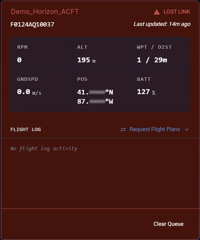
Lost Link — no telemetry has arrived for the last 5 minutes. The card renders red with a Lost Link warning and shows the last known values and their age.
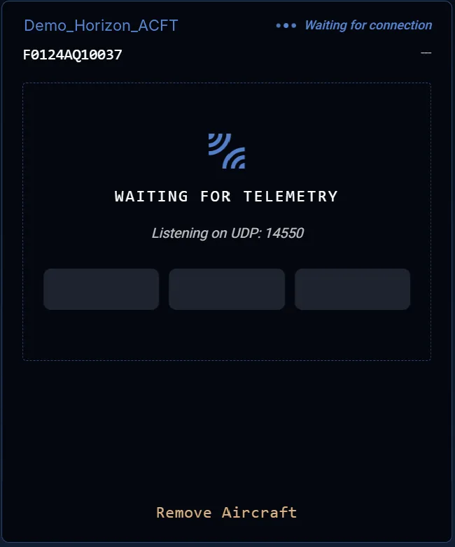
Waiting for connection — configured but no telemetry yet. The card shows the port it is Listening on UDP and reports progress as Waiting for telemetry, then Connecting to GCS, with a Remove Aircraft control.
In Fleet View multiple aircraft appear side by side — here one Active aircraft beside one still Connecting to GCS.
Flight Log states
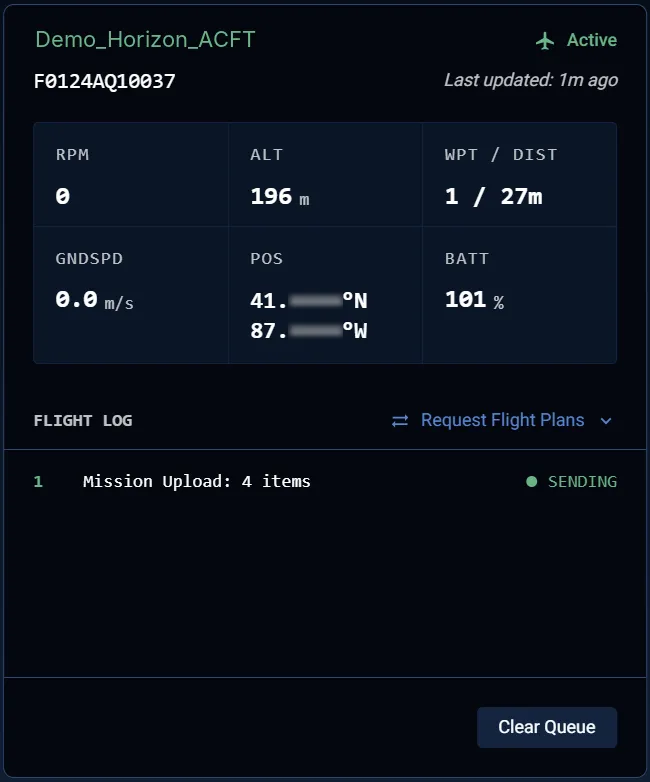
The Flight Log records each command sent to the aircraft and each system event. Command entries advance through Pending → Sending → Delivered; system entries (for example, Flight plan requested / received) are labeled System.
While a command is in flight — here Mission Upload: 4 items — its status reads Sending and the header control shows Requesting….
Once the aircraft acknowledges, the entry reads Delivered, and any resulting system events (Flight plan received: mission) are appended.
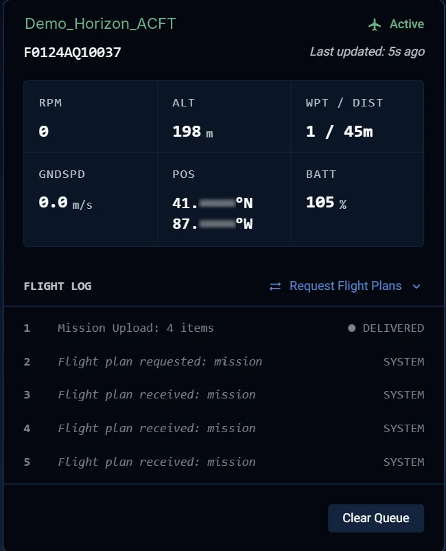
A Delivered entry is a positive delivery receipt — the aircraft confirmed it received the package. Confirmed entries persist in the log (dimmed) rather than clearing, so the Flight Log is a record of what was actually delivered, not just transmitted.
Requesting a flight plan
The Request Flight Plans control retrieves a plan from the aircraft. Choose the plan type from its drop-down — Mission, Geo Fence, or Rally Points — and Horizon UI buffers the retrieval across multiple BLOS messages, showing Requesting… until it completes. For the full procedure see Requesting a Flight Plan Over BLOS.
Aircraft detail
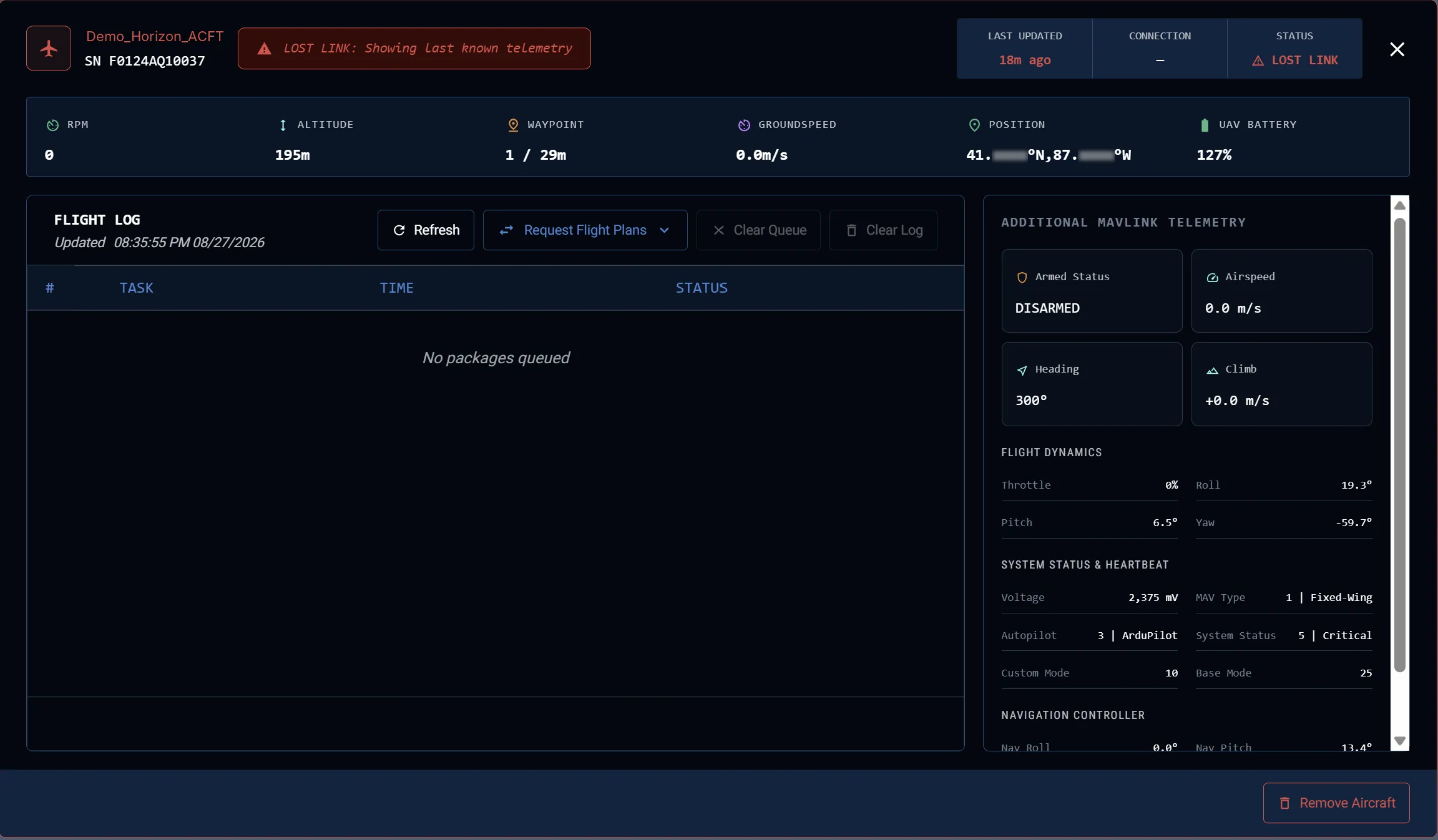
Selecting a card opens the aircraft detail view. The top band repeats Last Updated, Connection (for example, BLOS), and Status (Live or Lost Link), above the full metrics row. The Flight Log here adds Refresh and Clear Log alongside Request Flight Plans and Clear Queue. The right panel, Additional MAVLink Telemetry, groups Armed Status, Airspeed, Heading, and Climb; Flight Dynamics; System Status & Heartbeat; and Navigation Controller.
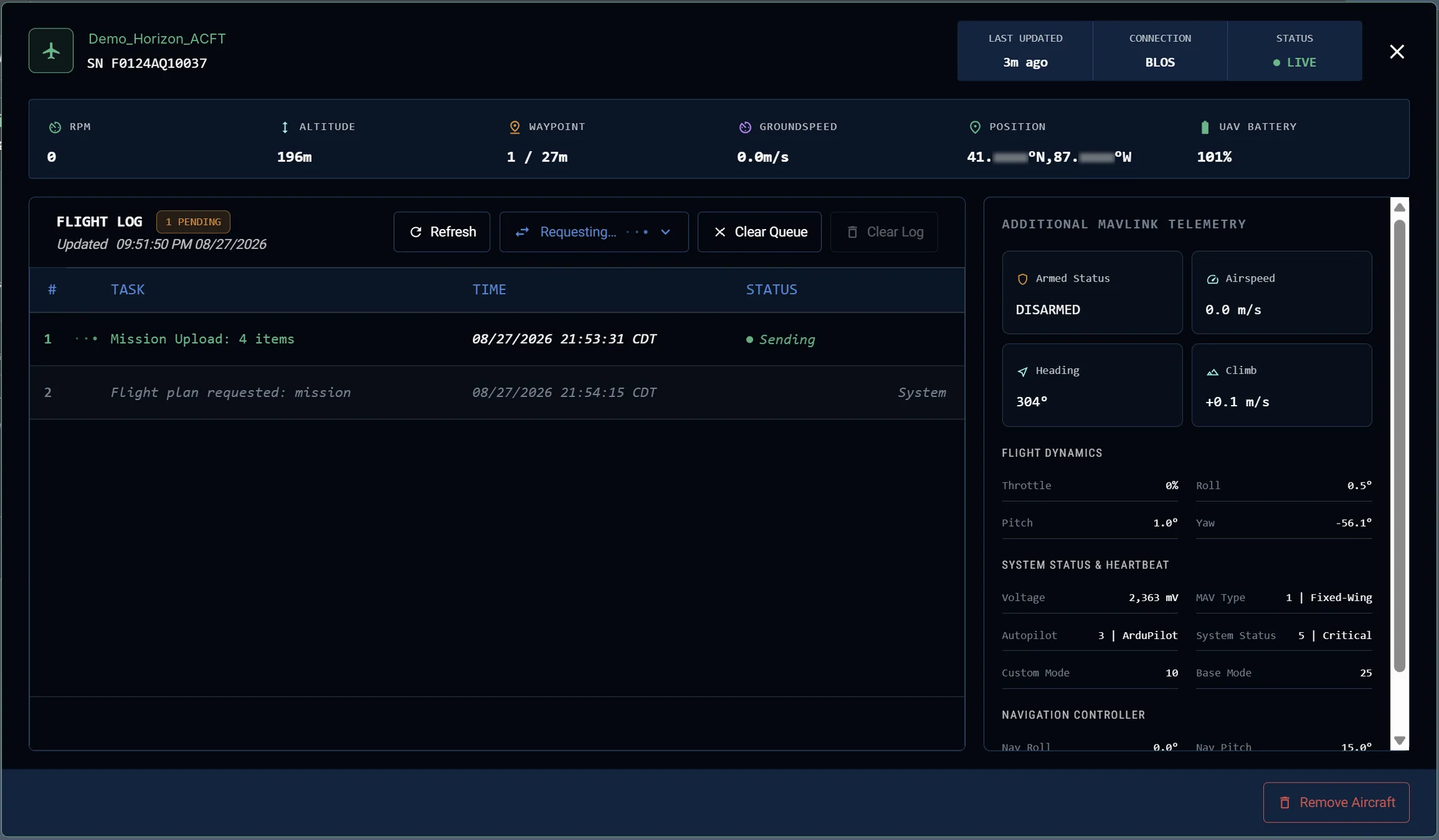
The detail view exposes two distinct queue controls. They perform different functions and are not interchangeable:
- Clear Queue — cancels pending outbound tasks that have not yet been sent. (Also available on the aircraft card.)
- Clear Log — removes the accumulated delivery receipts — the completed, dimmed entries — from the bottom of the log. It does not cancel anything in flight.
In Lost Link, the detail view banners Lost Link: Showing last known telemetry and freezes the last received values.
Removing an aircraft
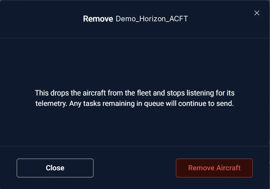
Remove Aircraft asks for confirmation. Removing an aircraft drops it from the fleet and stops listening for its telemetry; any tasks still in its queue continue to send. Queued tasks clear automatically after 12 hours of non-activity.
Preferences (GCS connection)
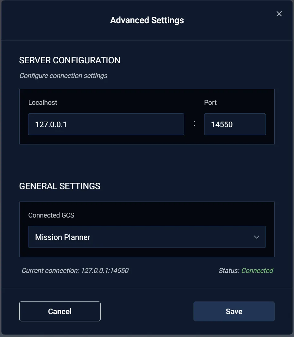
Preferences configures how Horizon UI connects to the GCS application. Under Server Configuration, Localhost and Port set the UDP endpoint (default 127.0.0.1 : 14550). Under General Settings, Connected GCS selects the GCS application (for example, Mission Planner). The footer shows the Current connection and Status (e.g. Connected). Save applies the change.
Diagnostics
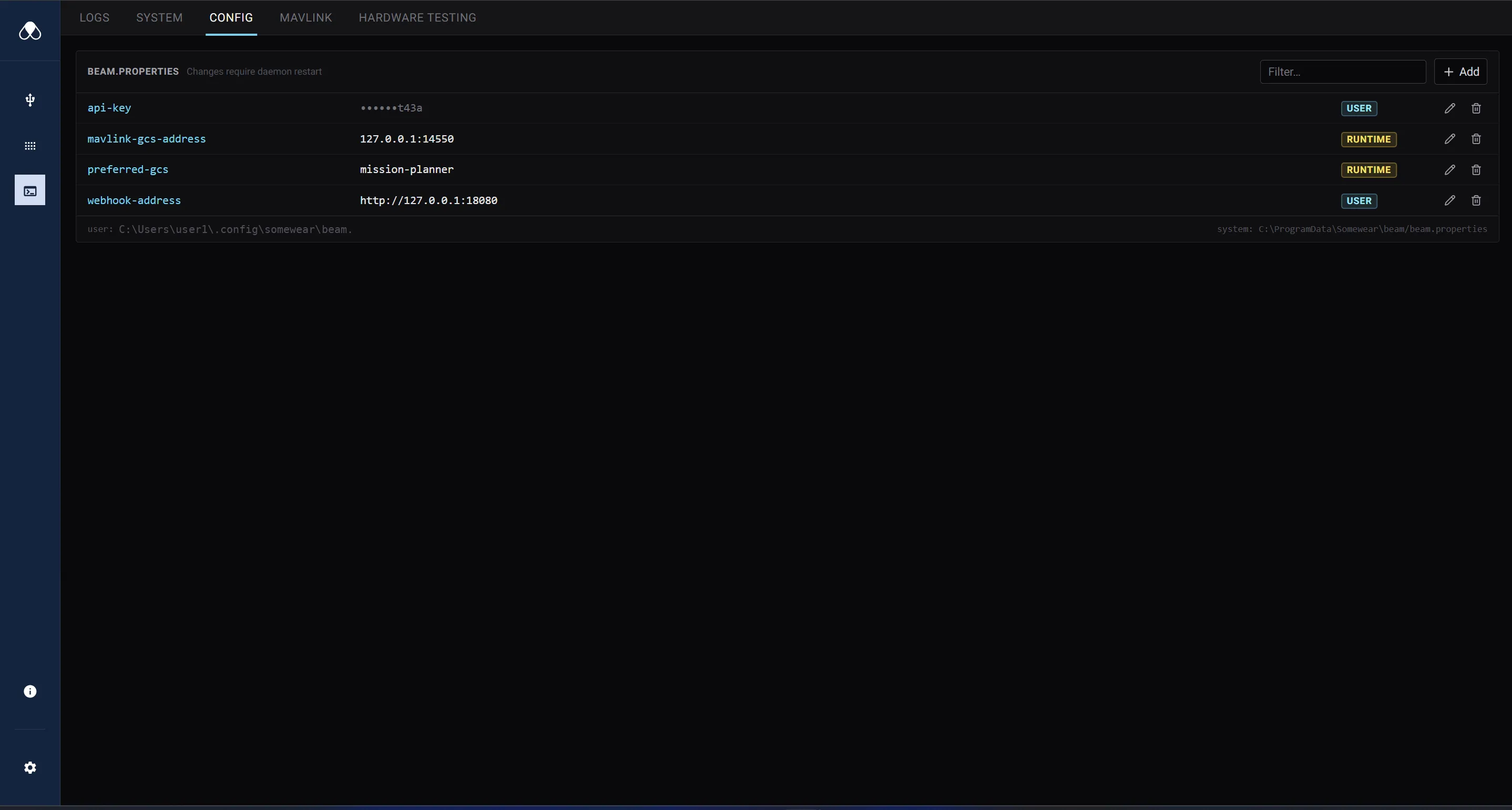
Diagnostics has five tabs: Logs, System, Config, MAVLink, and Hardware Testing. The Config tab edits beam.properties (changes require a daemon restart). Each row is a key with a scope tag — USER or RUNTIME — and Add / Filter controls. Keys include api-key, mavlink-gcs-address, preferred-gcs, and webhook-address. The footer shows the user and system beam.properties file paths.