
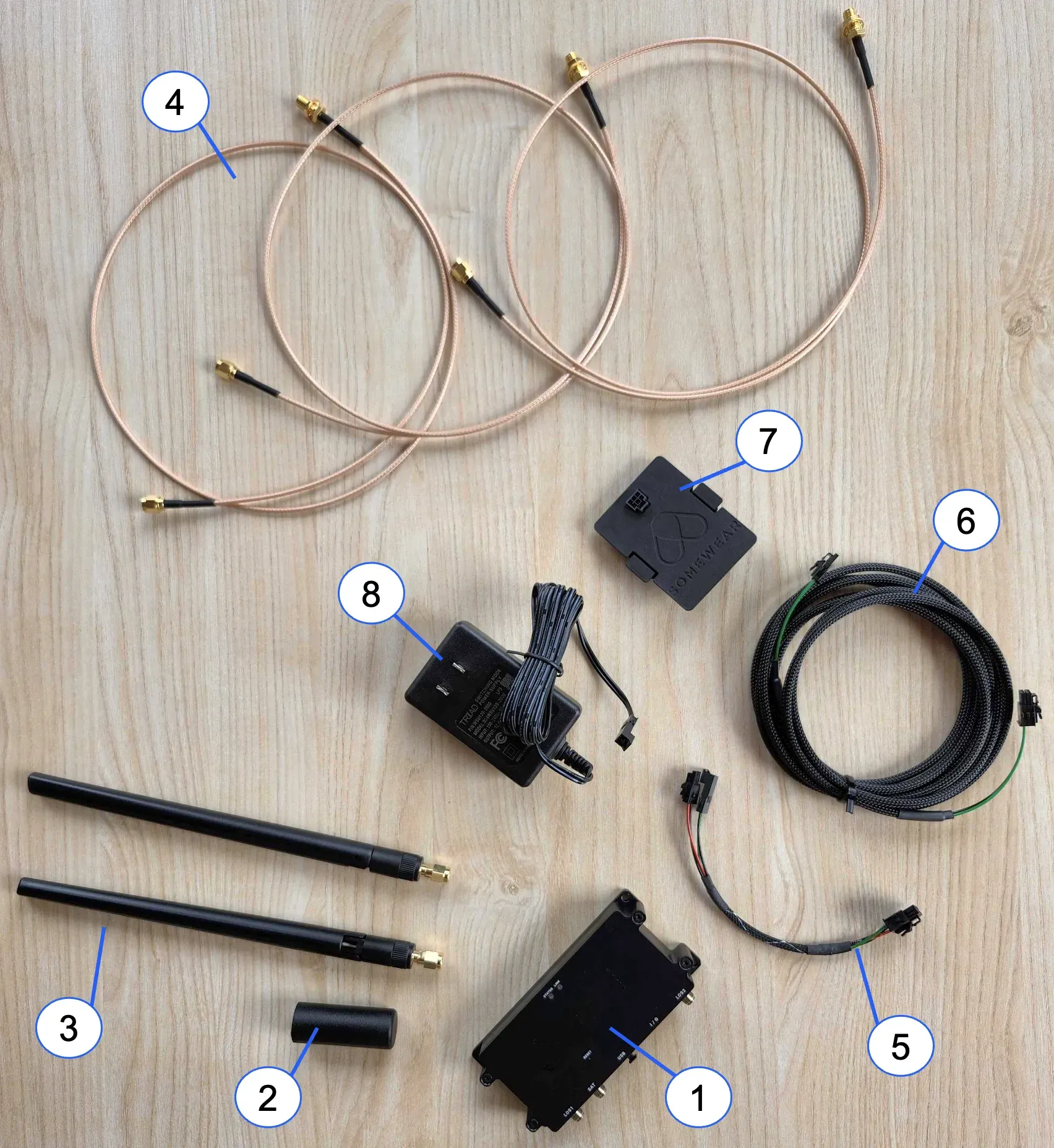
Every GCS-firmware Horizon unit ships with the same accessory kit, shown below. For the full parts list and specifications, see GCS Hardware Unit Kit.
RC Controller Backpack Assembly
The GCS kit includes a Somewear-supplied “backpack” assembly (SWL-50019) — a 3D-printed plastic cover that replaces the default rear cover on the Taranis RC controller. The backpack provides the connector pass-through for the Somewear RC controller cable (SWL-HAR-0004). Install the backpack before connecting the controller to the GCS Hardware Unit.
Antenna Setup
- Mount the two 915 MHz LOS whip antennas on a suitable elevated structure (e.g., user-supplied tripods or masts — not included in the GCS kit).
- Use antenna mounts compatible with the chosen tripod or mast.
- Attach one 915 MHz whip antenna to each mount. Where possible, orient the two antennas at right angles to one another to gain polarization diversity.
- Connect SMA coaxial cables from the antennas to the LOS1 and LOS2 ports on the GCS Hardware Unit.
- Connect the GCS BLOS (Iridium/Inmarsat) antenna to the SAT port. The SAT connection is required for BLOS control unless the GCS computer has active ISP/internet connectivity, in which case BLOS commands can be routed through the Somewear backend instead.
RF coaxial cables carry sensitive signals and must be routed carefully. The coaxial shield attenuates interference but may still pick up common-mode noise, which degrades RF performance.
- Do not route RF cables parallel and in close proximity to cables carrying high current or unshielded, unbalanced high-speed digital signals.
- Keep RF cable runs as short as practical. Maximum recommended BLOS feedline loss is 3 dB.
BLOS link quality depends heavily on a clear view of the sky. This is generally less of a concern for airborne units than for the GCS.
- Avoid testing or operating BLOS indoors, surrounded by tall buildings, or under heavy tree canopy.
- Iridium coverage is global, including polar regions. Inmarsat coverage is global between approximately ±82° latitude — GCS antenna placement should account for the look angle to the appropriate Inmarsat satellite.
Computer Connection
- Connect the GCS Hardware Unit to the GCS laptop using a data-capable USB-C cable (user-supplied — not included in the kit; see GCS Hardware Unit Kit). The USB-C connection provides the computer interface only — it does not power the unit.
- Connect the GCS Hardware Unit I/O connector VSUPP (pin 1) and GND (pin 7) to a regulated DC supply within the 6–13V operating range. Somewear Labs recommends the Triad Magnetics WSU120-2000 for bench/GCS use.
- Power on the GCS Hardware Unit. The unit powers on automatically once the DC supply connection is made.