
General Guidance
Flight Controller Connection
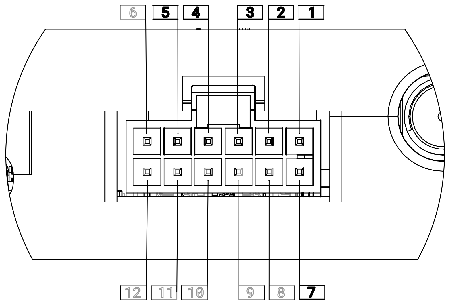
- Connect the flight controller interface cable to the TELEM1 port on the flight controller board. The I/O connector is a 12-pin Molex Nano-fit. Refer to Hardware Description for the full pinout. Connect UART_TX (pin 4) to TELEM1 TX and UART_RX (pin 5) to TELEM1 RX . For hardware flow control, connect UART_RTS (pin 2) to RTS output and UART_CTS (pin 3) to CTS input.
- Connect VSUPP (pin 1) to the positive supply and GND (pin 7) to the negative/return lead of a 2S/3S LiPo battery or a high-quality regulated supply (6–13V DC).
| Pin | Name | Type | Description |
|---|---|---|---|
| 4 | UART_TX | Output | UART TX data line |
| 5 | UART_RX | Input | UART RX data line |
| 2 | UART_RTS | Output | UART hardware flow control — RTS output from radio |
| 3 | UART_CTS | Input | UART hardware flow control — CTS input into radio |
| 1 | VSUPP | Power | Main power input (6–13V DC) |
| 7 | GND | Power | Power/signal ground — recommended: VSUPP return lead |
Aircraft Mounting
Thermal Considerations
The unit requires no intensive thermal management, but must not be thermally coupled to other heat-generating devices without provisions for supplemental cooling.
EMI Considerations
The Horizon Hardware Unit contains board- and enclosure-level EMI shielding, but this shielding does not provide perfect isolation.
Horizon should not be mounted in close proximity to significant sources of electromagnetic interference, such as spark-ignition engines and their ignition systems, brushed DC motors, large brushless DC motors, electronic speed controllers (ESCs), and alternators.
Additionally, avoid co-locating Horizon with other radios operating within the 902-928 MHz LOS tuning range or the 1616–1626.5 MHz BLOS tuning range. If co-location is unavoidable, frequency deconfliction measures must be taken.
RF coaxial cables carry sensitive signals and must be routed carefully. The coaxial shield attenuates interference but may still pick up common-mode noise, which degrades RF performance.
- Do not route RF cables parallel and in close proximity to cables carrying high current or unshielded, unbalanced high-speed digital signals.
- Keep RF cable runs as short as practical. Maximum recommended BLOS feedline loss is 3 dB.
BLOS link quality depends heavily on a clear view of the sky. This is generally less of a concern for airborne units than for the GCS.
- Avoid testing or operating BLOS indoors, surrounded by tall buildings, or under heavy tree canopy.
- Iridium coverage is global, including polar regions. Inmarsat coverage is global between approximately ±82° latitude — GCS antenna placement should account for the look angle to the appropriate Inmarsat satellite.
Antenna Placement — Aircraft
- Connect the two 915 MHz whip antennas to the LOS1 and LOS2 ports using the provided RP-SMA-to-SMA adapters and SMA coaxial extension cables.
- Connect the Iridium satellite antenna to the port labeled SAT using an SMA coaxial cable.
- Mount antennas to the aircraft airframe. Exterior mounting is preferred for all antennas; interior mounting is acceptable only if RF permeability of the compartment is specifically engineered. Ensure the Iridium antenna has an unobstructed view of the sky, with its main radiation lobe pointed toward the sky — consult the antenna datasheet for radiation pattern.
- Maintain at least 33 cm (~1 wavelength at 915 MHz) of separation between each LOS antenna and nearby conductive objects, and at least 19 cm (~1 wavelength at 1.6 GHz) of separation between the BLOS antenna and nearby conductive objects.
- Separate the two LOS antennas by a minimum of 8 cm. Where possible, orient them at right angles to one another (e.g., one vertical, one horizontal) to gain polarization diversity.
Power-On Verification
- Power on the aircraft and flight controller.
- Confirm the STATUS LED on the Aircraft Hardware Unit turns solid green (power good).