
Use Payload Control to switch payloads on and off from a mission plan (e.g. on arrival at a waypoint) or by hand. This feature can control the LOS radio, BLOS satellite link, or also an external payload connected to Horizon’s GPIO. Payload Control lets a mission plan or operator switch the aircraft’s You set it up in three stages: map each piece of equipment to an output index in Horizon UI, configure a matching relay on the autopilot, then actuate it from Mission Planner.
What you’ll need
- Horizon UI 1.15.0 or later, with the Horizon unit connected over USB (see Configure Horizon).
- Autopilot firmware — ArduPilot v4.5.0+ or PX4 v1.14.0+. Equipment-channel control does not work on older versions.
- Mission Planner (or an equivalent ground control application, or “GCS”) connected to the flight controller.
- The flight controller’s serial port already configured for the Horizon link (see Flight Controller Configuration).
Indexing
Each equipment channel is identified by a number in three places, and the number is not the same in all three. Get this wrong and the relay UI will appear to work while the payload never switches.
| Where | What you enter | Value to use |
|---|---|---|
| Horizon UI → Output Index | The index you assign to a channel | your choice, 1–64 |
Autopilot → RELAYx parameter | The relay you configure | Output Index + 1 |
Mission plan → DO_SET_RELAY | The relay a plan actuates | the Output Index |
| Direct actuation → Servo/Relay tab | The relay you toggle by hand | RELAYx = Output Index + 1 |
Map equipment to output indices in Horizon UI
The Advanced Settings modal in Connected Device holds both the serial-link settings and the equipment map. (This is separate from Preferences, which sets the GCS connection — see the Horizon UI Tour.)
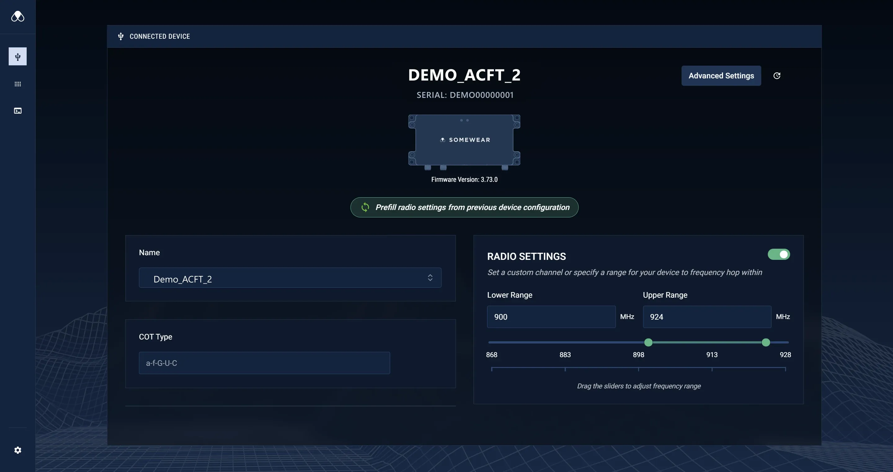
- In Connected Device with the unit attached, select Advanced Settings.
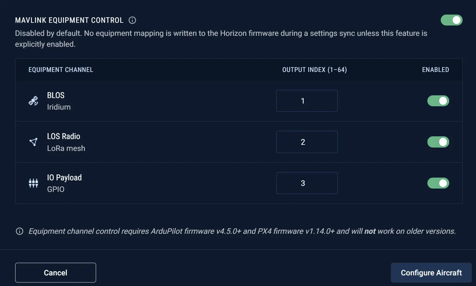
- Turn on MAVLink Equipment Control. While it is off, no equipment mapping is written to the Horizon firmware during a settings sync.
- For each channel you want to control — BLOS (Iridium), LOS Radio (LoRa mesh), and IO Payload (GPIO) — set an Output Index and enable its toggle.
- Select Configure Aircraft to write the mapping to the unit.
Note the index you assign to each channel — you will use it, and its + 1 relay number, on the autopilot.
The Advanced Settings button sits at the top right of Connected Device.
Each channel — BLOS, LOS Radio, and IO Payload — takes an Output Index and an Enabled toggle.
Set the serial link (baud rate and hardware flow control)
The Serial Link section of the same Advanced Settings modal sets how the Horizon unit talks to the flight controller.
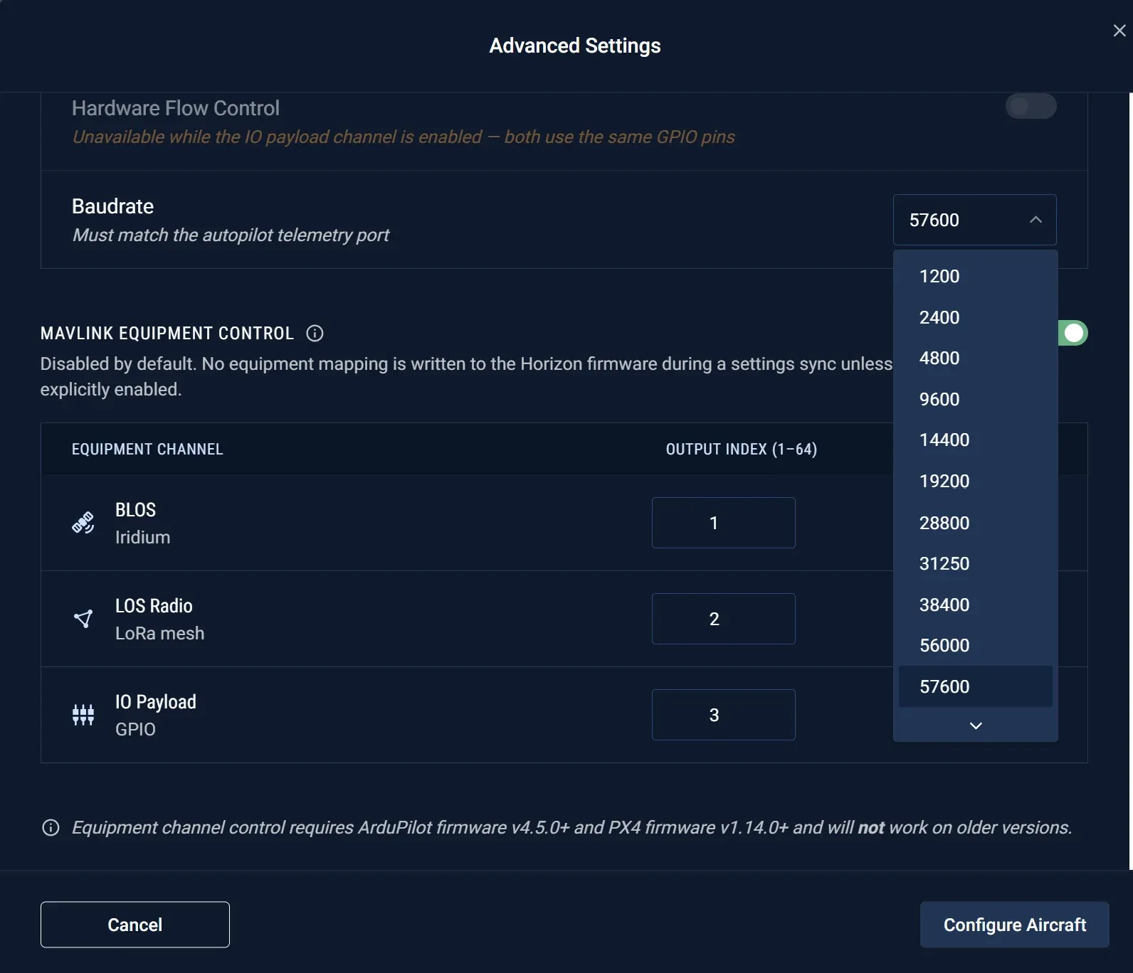
- Baudrate — must match the autopilot telemetry port; see Flight Controller Configuration (
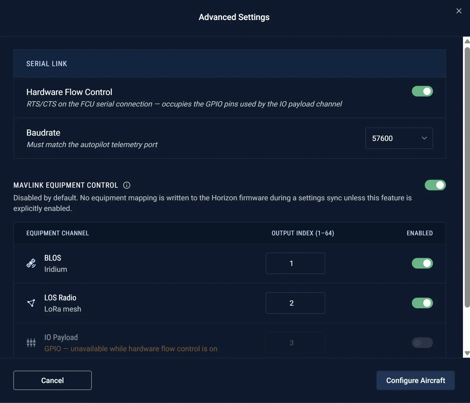
SERIAL1_BAUD) for the value the standard Horizon link requires. - Hardware Flow Control — RTS/CTS on the flight-controller serial connection. This is the setting that matters for payload control — see below.
The Baudrate dropdown lists the standard rates; select the one that matches the autopilot telemetry port.
With hardware flow control on, the IO Payload row is greyed out and its toggle is forced off.
Configure the autopilot relay (ArduPilot)
For each equipment channel you mapped in Horizon UI, configure the matching relay on the autopilot. Remember the relay number is the Output Index + 1.
-
Identify a physical output pin on the flight controller that is available for assignment (see the pin tables in C.5).
-
In Mission Planner, open Config → Full Parameter List (or Full Parameter Tree).
-
Set the chosen output’s
SERVOn_FUNCTIONparameter to-1to put the channel in GPIO mode. Leave anyTRIM,MIN, orMAXparameters for that channel unchanged. -
Configure the logical relay (
x= Horizon UI Output Index + 1):Parameter Value RELAYx_FUNCTION1RELAYx_PIN(pin value from C.5) RELAYx_DEFAULT0RELAYx_INVERTED0 -
Write the parameters to the flight controller and reboot the autopilot.
-
Verify from Mission Planner before relying on it in a plan.
In the Full Parameter Tree, each RELAYx shows its _FUNCTION, _PIN, and _DEFAULT. The _PIN dropdown lists every selectable output — the numeric values in the next section correspond to these entries.
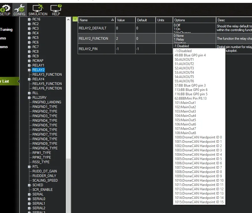
Relay pin values by autopilot board
Use the numeric RELAYx_PIN value for the output pin you identified in C.4. The configuration is conceptually identical across boards, but the available pins differ — confirm the values for any board not listed here against its documentation.
Cube Orange / Pixhawk family
Prefer an AUX output when one is available; otherwise use an unused MAIN output.
| Output | ArduPilot channel | Required setting | RELAYx_PIN |
|---|---|---|---|
| AUX OUT 1 | SERVO9 | SERVO9_FUNCTION = -1 | 50 |
| AUX OUT 2 | SERVO10 | SERVO10_FUNCTION = -1 | 51 |
| AUX OUT 3 | SERVO11 | SERVO11_FUNCTION = -1 | 52 |
| AUX OUT 4 | SERVO12 | SERVO12_FUNCTION = -1 | 53 |
| AUX OUT 5 | SERVO13 | SERVO13_FUNCTION = -1 | 54 |
| AUX OUT 6 | SERVO14 | SERVO14_FUNCTION = -1 | 55 |
| MAIN OUT 1 | SERVO1 | SERVO1_FUNCTION = -1 | 101 |
| MAIN OUT 2 | SERVO2 | SERVO2_FUNCTION = -1 | 102 |
| MAIN OUT 3 | SERVO3 | SERVO3_FUNCTION = -1 | 103 |
| MAIN OUT 4 | SERVO4 | SERVO4_FUNCTION = -1 | 104 |
| MAIN OUT 5 | SERVO5 | SERVO5_FUNCTION = -1 | 105 |
| MAIN OUT 6 | SERVO6 | SERVO6_FUNCTION = -1 | 106 |
| MAIN OUT 7 | SERVO7 | SERVO7_FUNCTION = -1 | 107 |
| MAIN OUT 8 | SERVO8 | SERVO8_FUNCTION = -1 | 108 |
ARKV6X (no-IOMCU firmware — built without the separate I/O co-processor)
Mission Planner’s labels for 50–57 may be generic or incomplete — use the numeric values below.
| Output | ArduPilot channel | Required setting | RELAYx_PIN |
|---|---|---|---|
| PWM 1 | SERVO1 | SERVO1_FUNCTION = -1 | 50 |
| PWM 2 | SERVO2 | SERVO2_FUNCTION = -1 | 51 |
| PWM 3 | SERVO3 | SERVO3_FUNCTION = -1 | 52 |
| PWM 4 | SERVO4 | SERVO4_FUNCTION = -1 | 53 |
| PWM 5 | SERVO5 | SERVO5_FUNCTION = -1 | 54 |
| PWM 6 | SERVO6 | SERVO6_FUNCTION = -1 | 55 |
| PWM 7 | SERVO7 | SERVO7_FUNCTION = -1 | 56 |
| PWM 8 | SERVO8 | SERVO8_FUNCTION = -1 | 57 |
Verify the relay from Mission Planner
Before trusting a relay to a mission plan, confirm it actually switches the payload — from the Servo/Relay tab on Mission Planner’s Data screen, while connected to the flight controller.
Each configured relay appears here as Relay x — using the RELAYx value (Output Index + 1), not the Output Index itself.
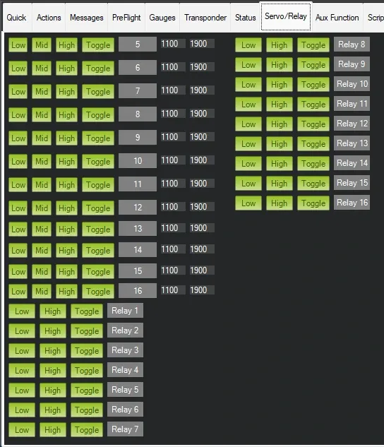
- Low commands the relay low (the box turns red) — the payload’s On state.
- High commands the relay high (the box turns green) — the payload’s Off state.
- Toggle sends Low, High, Low in sequence; we do not recommend using this setting.
Actuate a payload from a mission plan (proximity trigger)
After confirming the configured relay switches the payload correctly, you can embed the actuation in a mission plan. This enables operations like disabling the LOS radio on entry to a defined area to reduce RF signature.
Relay state: 1 = Off, 0 = On. (Each equipment channel’s default output is treated as On.)
- In Mission Planner, plan the mission up to the waypoint
Nwhere the change should take effect. Set that waypoint’s lat / long / alt to the trigger location. - Immediately after waypoint
N, insert a new mission item and set its Command toDO_SET_RELAY. - Set Relay No to the Horizon UI Output Index for the equipment — not the
RELAYxvalue. Set the relay value to1to switch the payload off, or0to switch it on.
DO_SET_RELAY will fire only after the preceding waypoint is reached; this enables automatic change based on location or altitude.
Troubleshooting
The relay appears configured but the payload doesn’t respond:
- Confirm the output pin is a real, unoccupied output — not one already wired to a servo, ESC, or other actuator.
- Confirm the Output Index is unique per channel in Horizon UI — BLOS, LOS Radio, and IO Payload each need their own.
- Confirm Hardware Flow Control isn’t silently disabling the IO Payload channel.
- Confirm the autopilot parameters were written and the autopilot rebooted.
- Re-verify from the Servo/Relay tab before suspecting the mission plan itself.
Related
- Configure Horizon — naming, radio settings, and firmware for the unit you configure here
- Flight Controller Configuration — the
SERIAL1baud and flow-control settings the serial link must match - Hardware Description — the I/O connector pinout, including the GPIO pins shared with hardware flow control
- Horizon UI Tour — where Advanced Settings and Preferences live in the interface