
Common Features (Both Units)
The Aircraft Hardware Unit and GCS Hardware Unit are identical hardware. The distinction between roles is determined by the firmware loaded on the device. Firmware files ending in _default configure the unit for aircraft use; files ending in _gcs configure it for GCS use. Units can be converted between roles by flashing the appropriate firmware (see Firmware updates).
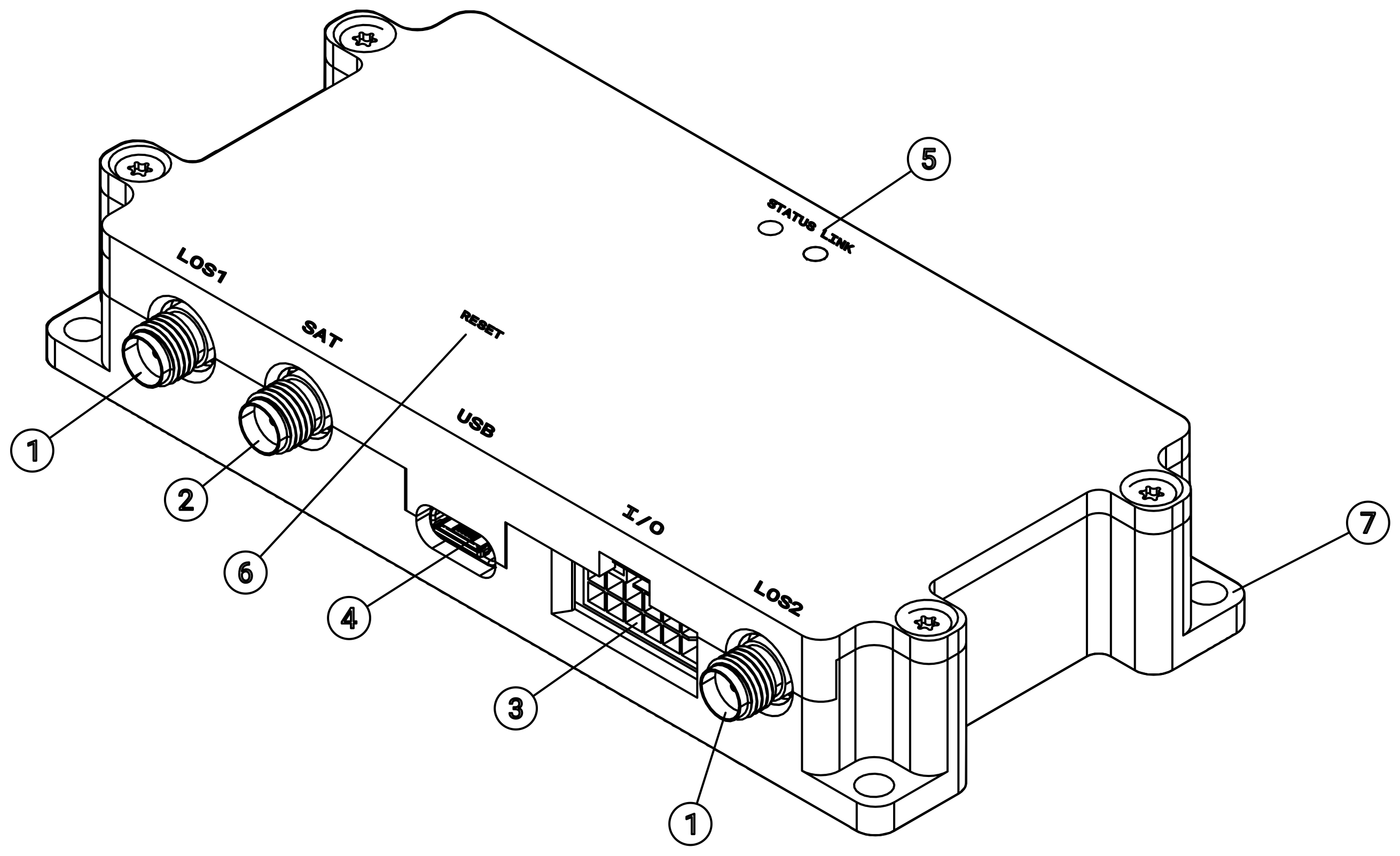
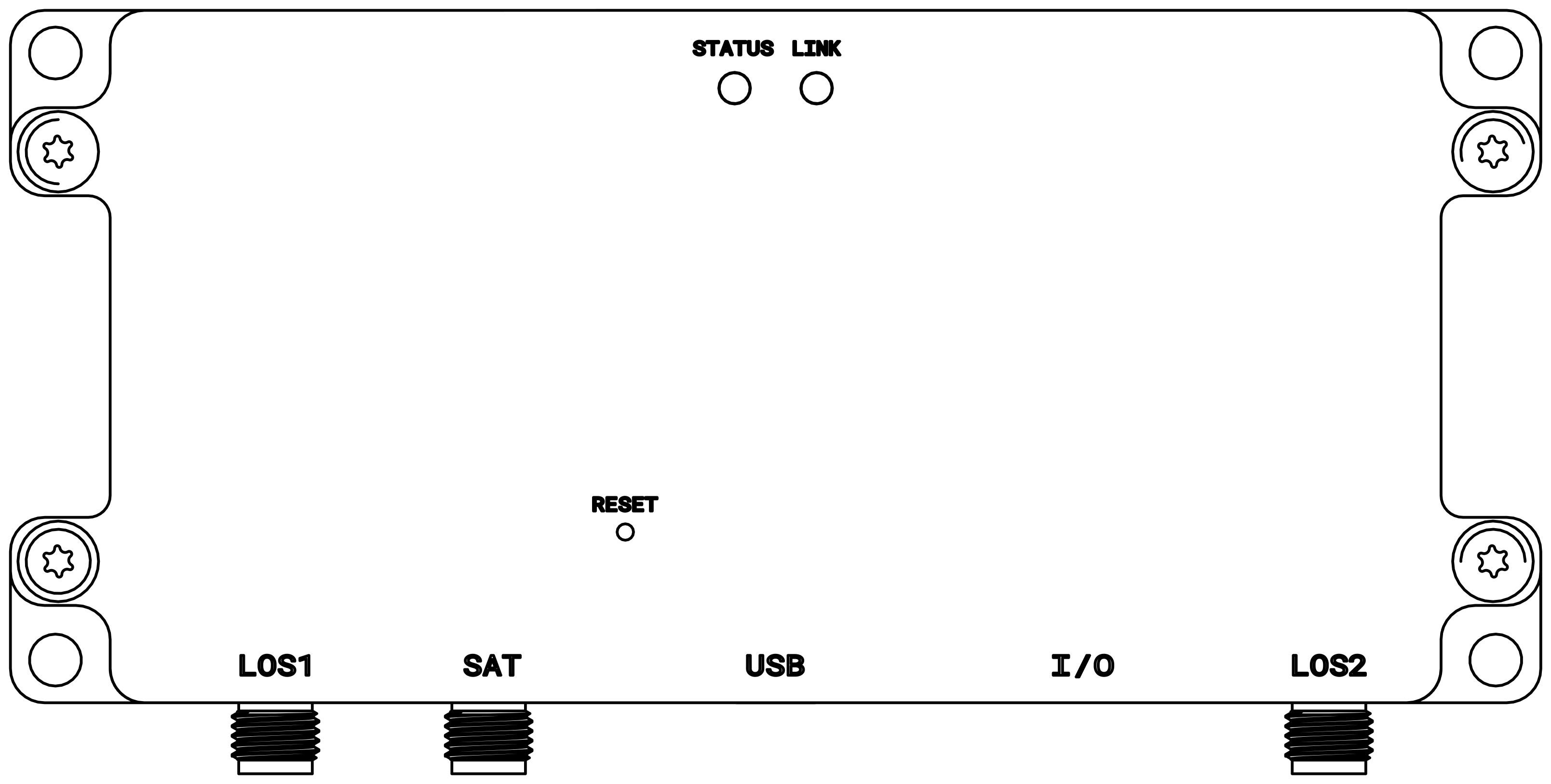
Callout Key
- LOS1 / LOS2 antenna ports (915 MHz, SMA female, standard polarity)
- SAT antenna port (Iridium / Inmarsat, SMA female)
- I/O connector (12-pin Molex Nano-fit; power, UART, digital I/O, 5 V accessory)
- USB-C port (computer interface; cannot supply unit power)
- STATUS and LINK LED indicators
- RESET button (also engages USB DFU mode)
- Mounting flange and through-holes
Connectors
| Port Label | Description |
|---|---|
| LOS1 | 868-928 MHz antenna, SMA |
| LOS2 | 868-928 MHz antenna, SMA |
| SAT | Iridium or Inmarsat satellite antenna, SMA |
| USB-C | Computer interface / firmware / configuration |
| Flight Controller Port | Aircraft telemetry interface (Aircraft Hardware Unit) |
| Power | 2S/3S battery or regulated supply input |
Horizon has two independent LED indicators. STATUS provides insight to overall device operation and LINK to LOS link connection.
STATUS LED
| Pattern | Meaning |
|---|---|
| 🟢 Solid Green | Power good (normal) |
| 🔴 Blinking Red | Bootloader mode (abnormal during operation) |
| 🟡 Flashing Amber | Firmware update in progress — do not unplug the device |
LINK LED
| Pattern | Meaning |
|---|---|
| 🟢 Blinking Green | LOS link connected |
| 🔴 Blinking Red | LOS link lost |
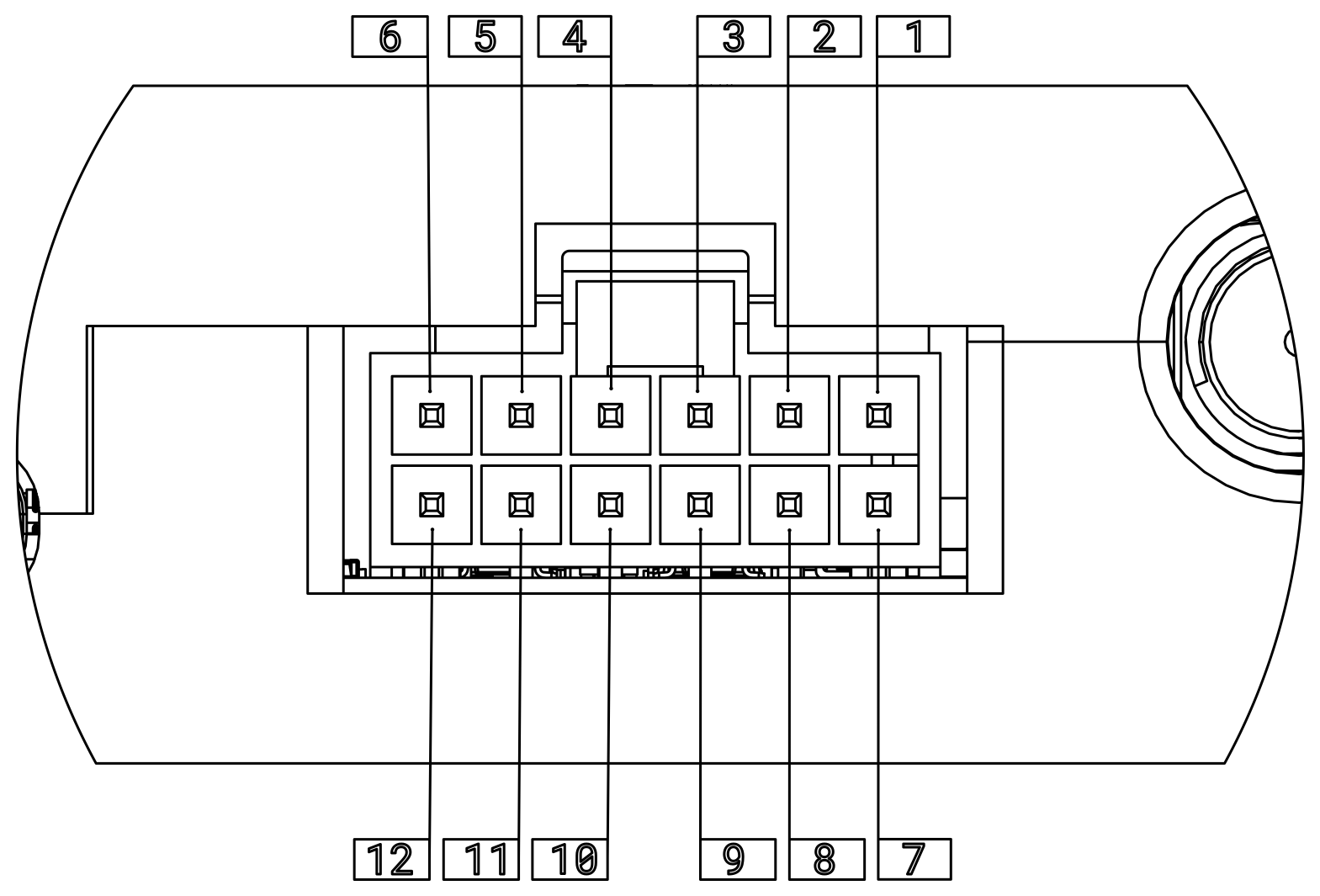
I/O Connector (Flight Controller / Power Interface)
The I/O connector is a 12-pin, right-angle Molex Nano-fit header. It is the primary interface for power input, flight controller UART communication, hardware flow control, digital I/O, and 5V accessory power output.
| Pin | Name | Type | Description |
|---|---|---|---|
| 1 | VSUPP | Power | Main power input (6–13V DC) |
| 2 | UART_RTS | Output | UART hardware flow control — RTS output from radio |
| 3 | UART_CTS | Input | UART hardware flow control — CTS input into radio |
| 4 | UART_TX | Output | UART TX data line |
| 5 | UART_RX | Input | UART RX data line |
| 6 | 5V_ACC | Power | Switched 5V output (for low-power accessories; max 250 mA recommended) |
| 7 | GND | Power | Power/signal ground — recommended: VSUPP return lead |
| 8 | GND | Power | Power/signal ground — recommended: UART/IO ground |
| 9 | GND | Power | Power/signal ground — recommended: 5V_ACC return |
| 10 | NC | — | Electrically unconnected. Do not connect. |
| 11 | DIGITAL_IN | Input | Dedicated digital input pin. User-configurable functionality. Defaults to SBUS input when the device is configured for GCS operation. |
| 12 | DIGITAL_OUT | Output | Dedicated digital output pin. User-configurable functionality. |
Connector Part Numbers
| Item | Molex Part Number |
|---|---|
| I/O connector on Horizon Hardware Unit | 1053141212 |
| Recommended mating connector housing | 1053081212 |
| Recommended crimp terminals (select by wire gauge) | 1053002100 or 1053001100 |
Reset Button
A small hole in the enclosure provides access to the device reset button. This button can also be used to engage USB Device Firmware Update (DFU) mode for firmware recovery.